DIY Van Build Electrical - SOLAR, SHORE POWER, BATTERY ISOLATOR
Just a dude with a vision but not a shirt
Hi, I want to help you figure out your build. That is why I am taking the time to write all these articles and make these videos.
I will do my best to walk you through the miracle that is my electrical system.
I am by no means an expert or even very knowledgeable. I am just a dude with a vision to get out on the open road, the stubbornness to push me through the scary parts of the van build, and no shirt.
Oh, also a few hundred hours of research and planning and now an actual adventure van that is working (so far).
I have pieced together the various major van life resources out there (Greg Virgoe, Explorists, Faroutride, Will Prowse, and many, many other various scattered tutorials and blogs etc.) to build my van and my electrical system.
I would suggest you take my resources and augment your own growing plan.
Or, copy me! Everything is working so far…
I watched these two videos about 47.3 times to help me put together my system. Thanks, Will!
OK, Let’s Do This!
Tools/Materials needed for this project —>
Hammer crimper for larger gauge wires
Cable stripper for larger wires
Hand crimper and stripper for smaller wires
Scissors for cutting wires (seriously, that’s what I used)
A hammer for the hammer crimper
Cordless drill with bits
Wood screws for mounting everything
Copper terminal connectors (I needed a few more 4AWG connectors so bought two sets of these)
Solar parts needed for this project —>
200watt Newpowa panels (x2)
MC4 connectors for wiring panels in parallel
I’m here for ya.
Seriously! Reach out on Instagram or YouTube with questions.
If reading bores you, take a break and watch the video!
Step 1:
Take a deep breath. You got this.
I did this and I have ZERO clue what I am doing / what I was doing before all of this.
Seriously, it’s likely the worst that will happen is you have to redo some work because you did it incorrectly.
You got this.
Step 2:
Prep the location of your battery bank / electrical system.
I had to put off building the electrical system until I had progressed the van build far enough to start constructing my kitchen since I had decided to build my whole electrical system under half the kitchen.
Where you put your battery bank is up to you. I went for under the kitchen since I knew I would already have a large box for the sink and stove and water system and storage.
Step 3:
Set all of your pieces out where they will need to go.
This was actually probably the hardest part of the entire electrical system.
I was standing at the sliding door with all my unopened electrical components spread out in front of me and suddenly the weight of the entire project settled on my mind and that voice in my head started talking about allllll the ways this could go wrong, all the holes in my knowledge.
Shut that voice up with some movement.
This part is where Will’s videos were especially helpful.
Through a process of elimination you can start organizing the chaos and making progress.
I set my batteries under a shelf just high enough to be able to manage the wires. The inverter would get mounted to the side of the cabinet to save space. The fuse block was close to where all my DC wiring would feed into the system (in the rear). The on/off switch was in the path of the positive terminal of the battery below. The charge controller was basically put into the space leftover. The bus bars were in the center of it all for easy access to all the various parts. The breakers and fuses were slowly placed where they would intercept the positive wires from all the parts (Will’s video helps with that). 40a breaker in-line with charge controller, 150a breaker in-line with positive bus bar and inverter and fuse block, 200a breaker in-line with main battery cable and the switch.
I even set terminal connectors out at each spot I would be connecting wires.
Once I had triple-thought about where everything was placed, I screwed each piece partly to the plywood (just one screw) to keep them from moving.
Step 4:
Wire your batteries.
I wired my batteries in parallel in order to increase the overall capacity of the bank (100ah + 100ah = 200ah capacity).
Take the 1ft of 2AWG wire and connect the positive of each battery terminal and then the same with the negative.
Take the 2ft of 1/0 cable and connect the positive and negative of the battery terminals with the other end of those wires safely tucked away until your system is ready to receive the battery cables (negative will go to your battery monitor shunt and then the bus bar, positive will go through a breaker, the switch and then to the positive bus bar).
Step 5:
Start cutting, crimping, and connecting positive cables.
I used 4AWG red and black for all of my main connections.
The process is quite simple. Take your coil of cable, hold one end up to the first connection point (let’s say the positive terminal on your fuse block), then run that wire to the terminal of the breaker it will connect to, you’re measuring out how much wire you need to cut, take a pen and mark the section on the wire that touches the destination terminal, cut the wire at your marked point (I literally just used household scissors), take a terminal connector and hold it next to the wire, mark where the metal of the connector stops on the insulation on the cable (that is how much insulation you will strip off the wire to be able to fit inside the terminal connector), take your cable stripper, cut around the cable at your mark, fit the bare copper of the cable into the terminal connector, hold it in there firmly and place it on your hammer crimper, hammer a few times until the connection is very solid (but not enough to destroy the terminal connector), wrap the whole thing tightly in electrical tape (without letting tape touch the circular hole where your connection to the terminal will be).
Alternatively, you could use heat shrink to seal these connections rather than electrical tape if you have a heat gun.
NOTE: On the thicker cables, it can be hard to twist them around to fit certain angles of connections. So, when crimping your terminal connectors, try to anticipate the angles at which they will sit when tightened down onto your terminals and crimp them at those angles accordingly.
Once I cut and fit all my positive cables, I did the same with the negative cables.
NOTE: The battery cables are still disconnected at this point to keep the system from being live while you’re working on it.
Step 6:
Ground your system.
I ran a 4AWG wire from my negative bus bar to a little piece of metal in the van wall near the battery bank to ground my system to the van.
Alternatively, you can ground the system (run a negative wire from your negative bus bar) by connecting to a little terminal/metal spoke on the back of your inverter).
To ground my system, I simply drilled a hole in said piece of metal, ran a bolt through (with a washer on the front and back side to increase surface area), put my negative wire terminal connector on top of the top washer, and then attached a nut on the back of the bolt to tighten the whole thing down.
Step 7:
Connect all your DC loads.
If you’ve pre-wired your van successfully, you should have a clump of DC wires (positive and negative wires) hanging nearby ready to be connected to your system. I used 10AWG speaker cable (pure stranded copper, the highest quality) throughout my van to connect to all my DC loads (fridge, maxxfan, lights, 12v sockets, wall fan,).
Your fuse block has positive and negative terminals. The positives are all in the front (toward where your 4AWG red wire connects and runs to your 150a breaker shared with the inverter) and the negatives are in the back.
NOTE: in my system, my blue DC wires are my negatives (“red”) and the black are the negative.
Simply attach terminal connectors to each of the wires and then screw them down onto your fuse block.
NOTE: the terminal connection points on the fuse block are not very large, so use the terminal connectors from your set that are big enough for 10AWG wire but have small enough terminal connection points (the circular part) to fit onto your fuse block.
You can crimp these smaller wire connectors using your hand crimper. Then wrap the connection in electrical tape.
NOTE: the wires are not live and carrying power until you insert your properly sized (check manuals or purchaser comments for each appliance’s correct size fuse) ATO blade fuses into each slot. Also, don’t touch your negative and positive ends to each other (on the side of the wire not connected to the fuse block) once you’ve connected the wires to the fuse block. That will short your ATO blade fuses.
Step 8:
Set up your battery monitor system.
Although not strictly essential to the functioning of your system, I would highly recommend installing a battery monitor system into your electrical system.
Not only will the temperature sensor warn you if things are going wrong at your battery terminal connection point, and the reports will help you plan for power usage on your adventures, but it is also just dang fun to monitor the system!
I can’t tell you how many times I just pop open the app or pick up the physical indicator and tap through all the screens to see what’s up in my system.
To install, find a good place in-line with your battery negative cable to screw down your shunt, hook up the battery negative cable to one terminal and then wire another negative from the other terminal to your negative bus bar.
The positive wire from the battery monitor system connects directly to the positive terminal on your battery.
There is one more wire that plugs into your shunt and into the back of your display. You can run that wherever you want (mount it in your wall or, as I did, simply hide it away with easy access but not permanent display).
Step 9:
Set up your shore power.
I saved some space on one of the cabinet walls for the shore power box (my Samlex 30a box). I measured and cut my 8AWG positive and negative cables from the back of the Samlex to the 40a breaker (positive wire) and negative bus bar (black wire) then mounted the box and 40a breaker.
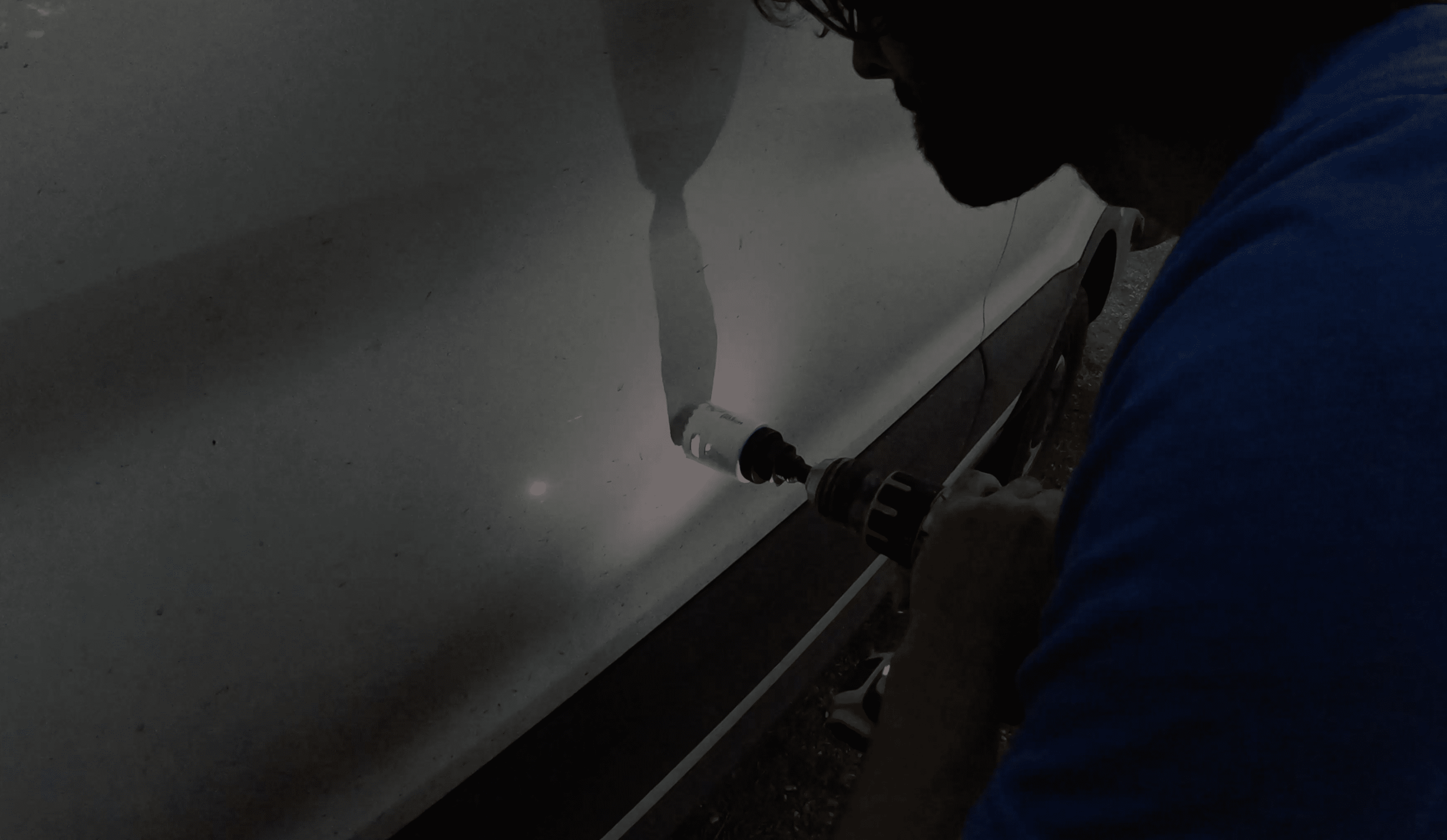
Later, I drilled my port hole on the outside of the van (using a hole saw drill bit thing, I still don’t remember the name) the same size as the diameter of the port.
Treat the raw metal with a Markal marker. Dry fit the port then run Butyl tape around the edges of the port (that will sit flush with the van side). Stick it against your van where you want it, then use self-taping sheet metal screws to tighten it against the van. Trim off the Butyl tape that squeezed out with a utility knife. Run a sealing bead of Through the Roof around the whole thing to seal it.
Then, simply connect the female plug on the back of your port to the male plug running off your Samlex power box inside the van and you are ready to go!
NOTE: when you first test this out, if your batteries are full the Samlex will not pull very much power at all. To test it, drain your batteries a bit or plug something into your inverter (I keep a 1000 watt pull panini maker nearby) to put a load on the system and watch the Samlex kick in!
Step 10:
Set up your battery isolator.
If you want to be able to charge your batteries while driving, this is what you will need to do.
Under your driver seat (if you have a Ford Transit) sit your car starter batteries. These are what you will be connecting to.
Uncover the back of the battery cover to access the car battery negative terminal. Disconnect this so that it is safe to work with the positive terminal.
Scoot the seat back now so you can access the positive terminal which sits toward the front of the driver seat base.
Attach your positive 4AWG wire to the positive terminal on your car battery and run that back to your system. This wire will first connect to a 150a breaker and then a 4AWG wire will connect from that breaker to the “STARTER BATTERY” terminal on the back of the battery isolator.
There will be a small negative cable running off the back of the battery isolator. Connect that to your negative bus bar or negative post on your fuse block (as I did).
Then run more 4AWG wire from the “SECOND BATTERY” terminal on the back of the battery isolator to your positive bus bar.
NOTE: If you wire this in reverse (the wire from the car battery to the “second battery” terminal and the wire from your van life batteries to the “starter battery” terminal, you will wake up one day and your car batteries will be dead since they would be trying to charge your van life batteries all on their own. Be warned.
Now, reconnect your negative cable on the car starter battery and the whole thing will go live!
NOTE: you will see a spark when you reconnect the negative cable to the car’s battery. You may also have reset your car’s time/date etc.
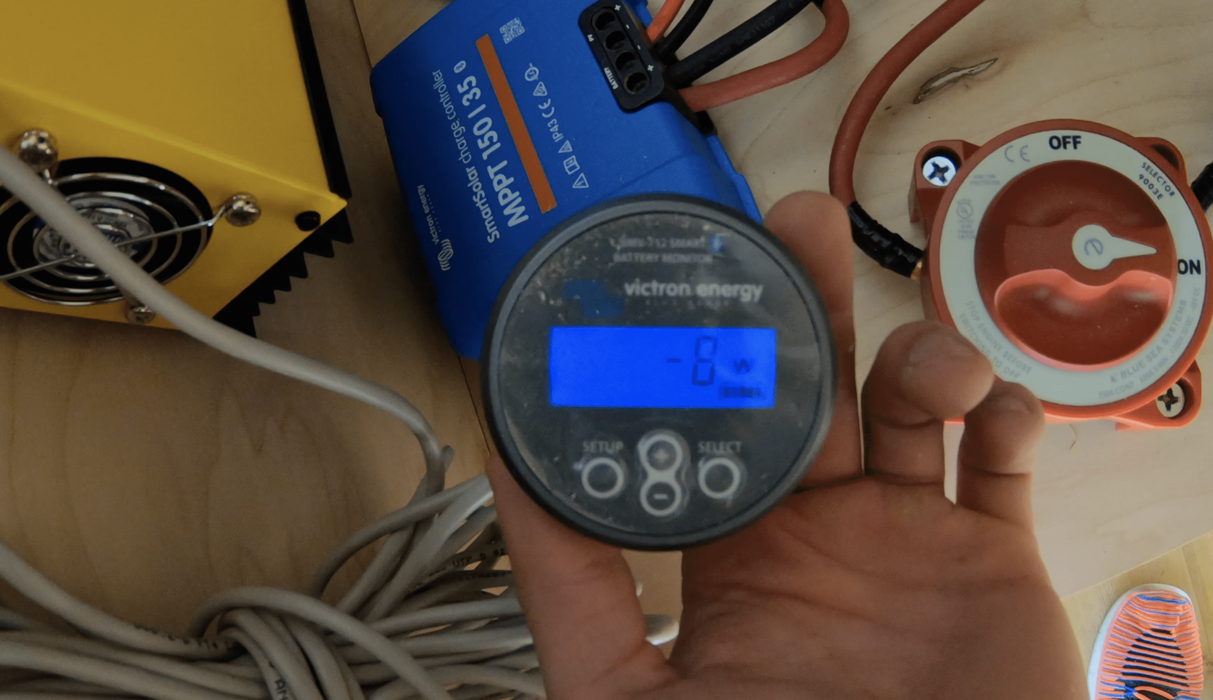
Once you have the whole system set up (with your batteries connected) you can grab your battery monitor display and watch the power flow as you start your car or leave it off but with accessories (like the radio) on.
NOTE: this battery isolator will now use your van life batteries to support your car starter battery. Meaning, if you are running lights or radio etc. in your car when the car ignition is off, the battery isolator will draw power from your van life batteries rather than the starter battery. Personally, I think this is AWESOME as it basically means I will never have a dead car battery ever again. Yay!
Step 11:
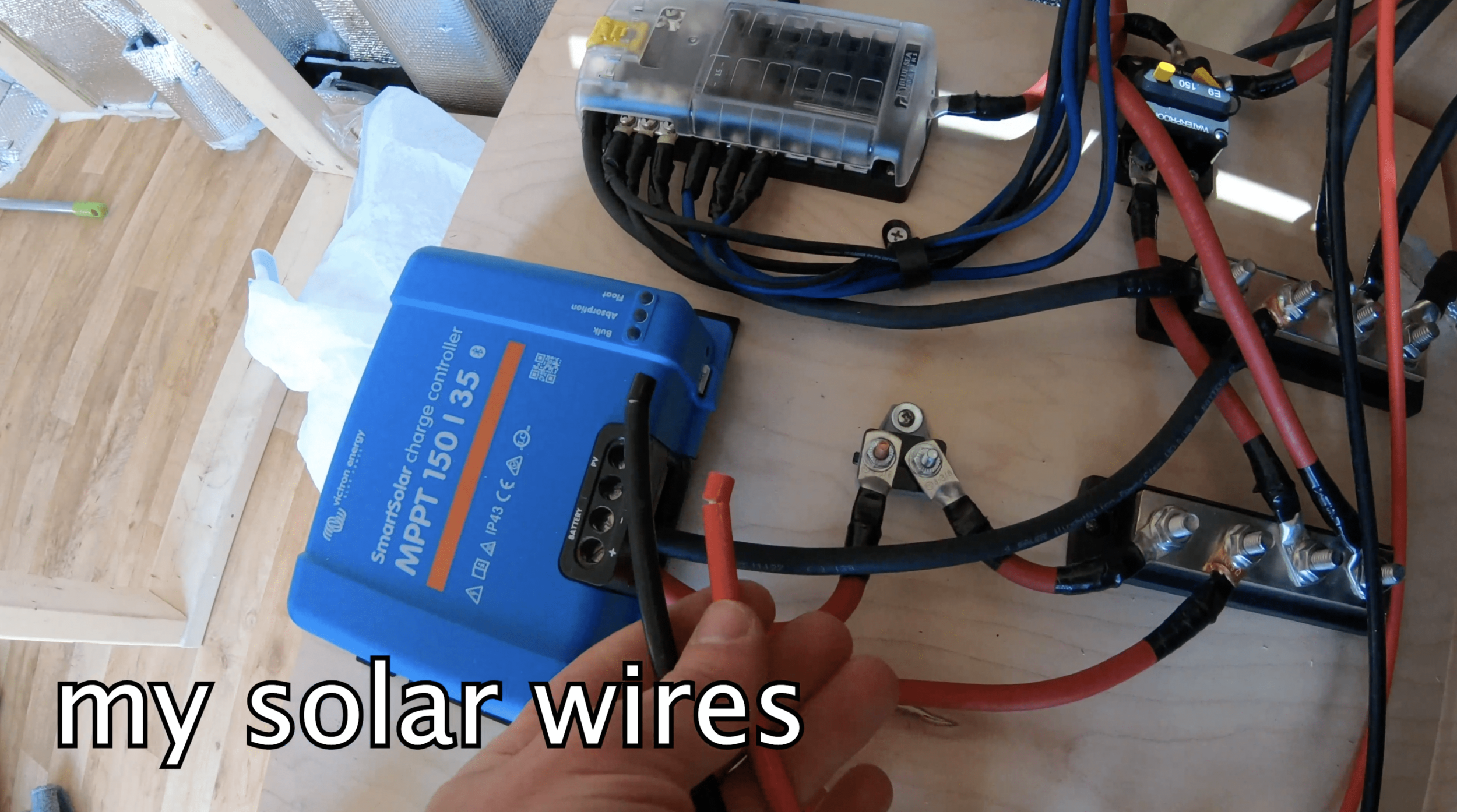
Connect your solar wires (coming from the panels) to the solar charge controller (which has already been wired into your system using that 4AWG wire).
Your solar charge controller has 4 connections ports: 2 (positive and negative respectively) for your cables running into your electrical system, and 2 for receiving the wires from your solar panels (also negative and positive respectively).
NOTE: just before connecting the solar cables to the charge controller, I connected my batteries to the whole system so that the power coming from the solar panels could have a place to go (the batteries).
I waited until the whole system was ready to go and then connected the wires from my solar panels to my charge controller because I read somewhere (in a long lost internet forum) that having the solar connected and power flowing WITHOUT a destination for that power (the batteries) is bad for the system…don’t quote me on that.
Final thoughts:
I once was a dude with no shirt and no electrical system. Now I’m a man with an electrical system.
Still no shirt, though. Is that even an issue?
I really hope this has proven useful to some people out there struggling to figure this out on their own (which I highly support as opposed to paying someone to do it for you).
I am extremely happy with my work and proud of it, quite honestly. If 6-months ago you would have told me that I’d be building out a van with a full self-sustaining electrical system inside…I’d have probably laughed in your face (then apologized).
If you want to know more or have questions, don’t hesitate to reach out! My Instagram is a good place to reach me or my YouTube.


